

1. Introduction
2. Overview of DCAS Regulation
2.1. DCAS Modes of Operation
2.2. Driver State Monitoring
2.3. Dynamic Control Features of DCAS
3. DCAS Testing and Evaluation
4. DCAS Expected Effects and Domestic Implementation Preparation
5. Conclusion
1. Introduction
Advancements in autonomous driving technology in recent years have facilitated the development of systems surpassing Level 3 of the SAE J3016 standard. However, Level 3 technologies have limitations that place excessive liability for on-road accidents on the manufacturer.(1) As advanced driver assistance system (ADAS) technologies mature, driver control assistance systems (DCAS) are emerging as a technical alternative between Levels 2 and 3 to address liability limitations. DCAS is a technology that falls under Level 2 of the SAE J3016 automated driving stages, but is designed to apply some elements of Level 3 technology to enhance safety and reduce manufacturer liability.(2) While conventional ADAS includes various functions to assist the driver in driving, DCAS is more than just an assistance system, it is a system that assumes continuous driver intervention while applying Level 3 autonomous driving technology to increase safety and reliability.(3) In this way, DCAS serves to support the realistic adoption of autonomous driving technology while maintaining driver responsibility. The UN R. 171 DCAS regulation defines the safety standards and requirements that manufacturers must comply with during the design and development process,(4) which must take into account standards related to functional safety and safety of intended function (SOTIF), such as ISO 26262 and ISO/PAS 21448 (SOTIF).(5,6) ISO 26262 specifies the functional safety of electrical and electronic systems in vehicles and is an essential standard for ensuring the hardware and software reliability of DCAS. ISO/PAS 21448 (SOTIF) is a standard for assessing safety risks that can occur even when vehicle systems are functioning normally, and as DCAS is designed to assist the driver, it plays an important role in reducing potential safety risks if the driver becomes overly dependent on the system.(7) To prevent excessive dependence on the system, DCAS must be designed to maintain driver trust while ensuring active driver engagement, which requires the introduction of a driver monitoring system utilizing human-machine interaction (HMI). Recent studies have reported that driver monitoring systems are becoming an integral part of the autonomous driving environment, and that real-time driver health monitoring and warning systems play an important role in accident prevention.(8) These systems continuously monitor driver attentiveness in real time, engage the driver in active driving through warning strategies, and safely stop the vehicle when necessary.(9) Studies have shown that driver intervention when using Lane Following Assist (LFA) features can lead to heterogeneity, which requires Collaborative Steering Control to minimize.(10,11) This can improve the way DCAS intervenes with the driver and increase the trust between the driver and the system. Furthermore, to ensure the reliability and safety of DCAS, comprehensive testing, including physical testing on test tracks and public roads, should be performed in compliance with the validation procedures prescribed by ISO 26262 and ISO/PAS 21448. In partially automated vehicles, driver monitoring systems are considered essential to ensure safety, and studies have shown that various tests and behavioral analysis are required.(12) These validation processes are aimed at proving that the design and performance of the system meet regulatory standards, as well as proactively identifying and improving potential risk factors in the system.(13~15)
This study aims to analyze DCAS-related regulations in depth and provide direction for manufacturers to develop technologies that comply with these regulations. In doing so, it aims to enhance the safety and reliability of DCAS technologies and lay the technical foundation for them to contribute substantially to the intermediate stages of autonomous driving.
2. Overview of DCAS Regulation
DCAS is a subset of Advanced Driver Assistance Systems (ADAS), comprising hardware and software that supports the driver by continuously managing the longitudinal and lateral movements of the vehicle. When active, DCAS supports the driving task, actively stabilizing or controlling the vehicle to reduce the driver’s workload and increase comfort. However, the system operates only within defined boundaries and does not completely replace the driving task, meaning the driver retains full responsibility for what happens while driving.
DCAS is classified as Level 2 partial automation according to SAE J3016, indicating that it can only perform a portion of the vehicle’s dynamic control. At Level 2, the driver must continuously monitor the vehicle’s operating status, perform the remaining dynamic controls, and intervene immediately if the system’s operating boundaries are exceeded. The DCAS assists the driver by performing longitudinal and lateral control during operation, however the driver remains ultimately responsible for controlling the vehicle. If the DCAS provides only longitudinal or lateral control, the system’s automation level is temporarily reduced from 2 to 1.
DCAS is discussed by the United Nations (UN) GRVA, and the versions of the DCAS document are shown in Table 1. This study is based on the latest available version, the November 2024 draft.
Table 1.
Timeline of DCAS Regulation Document
2.1. DCAS Modes of Operation
During DCAS operation, certain system functions must be in Active or Stand-by mode, and some other system functions can remain in their existing state. While DCAS is in Active mode, continuous longitudinal and lateral control support must not be provided by any system other than the DCAS unless intervention by an emergency safety system is necessary.
The system can switch to Active mode only if all prerequisites outlined in Fig. 1. are met. These conditions include the driver being seated in the driver’s seat, wearing a seat belt, the driver monitoring system functioning properly, no system errors detected, and the system operating normally within the specified boundaries. If the prerequisites for maintaining Active mode are not met, the system must switch to Stand-by mode and terminate control outputs in a safe and appropriate manner. The manufacturer may establish additional prerequisites as necessary to enhance system safety and reliability.

2.2. Driver State Monitoring
DCAS should be designed to keep the driver continuously and actively engaged in the driving task, monitoring the driver’s attention in real time and prompting immediate responses through alerts to mitigate the safety risks associated with over-reliance on the system. In particular, the system must detect and effectively respond to driver disengagement across various road conditions and complex traffic scenarios.
Driver State Monitoring (DMS) is a key component of DCAS, which tracks the driver’s gaze and head posture to assess attention in real-time. DMS detects when a driver is not adequately focused on driving and provides a warning strategy based on this. Warnings can be escalated or, depending on the situation, multiple warnings can be provided simultaneously. In addition, if there are already active warnings, new warnings can be suppressed or adjusted to ensure that the driver is appropriately informed. The proposed warning strategy is shown in Fig. 2.

Hands On Requests (HOR) is activated when the system detects that the driver has not engaged in driving for more than 5 seconds when the vehicle speed is 10 km/h or higher. However, HOR can be delayed up to 5 seconds if the system determines that the driver remains visually engaged. If the driver continues to disconnect, an expanded HOR shall be provided within 10 seconds of the initial HOR, which shall include additional audible and tactile information.
Eyes On Requests (EOR) are triggered when the driver remains visually disengaged for more than 5 seconds when the vehicle speed is 10 km/h or greater. If the visual disengagement persists, the warning must be escalated within at least 3 seconds of the initial EOR. The enhanced EOR must include audible and tactile information.
Direct Control Alerts (DCA) must be clearly and conspicuously presented to the driver to immediately resume lateral control of the vehicle and must be delivered within a maximum of 5 seconds after the EOR is escalated. In addition, a DCA is considered successful when the driver assumes direct control of the vehicle as requested and maintains operation without continuous lateral assistance.
Transition to Driver Unavailability Response: If the system detects that the driver remains unresponsive after the alert escalation, it must initiate a Driver Unavailability Response within 10 seconds of the first escalation request or DCA.
Driver Monitoring System (DMS) plays a crucial role in ensuring proper use of the system. To support this, manufacturers should provide user manuals, video guides, training materials, etc. to help drivers use the system safely.
2.3. Dynamic Control Features of DCAS
The DCAS must be designed to maintain the vehicle’s stability within the travel lane when activated and ensure that lateral acceleration does not exceed the limits set by the manufacturer. The system must be capable of adjusting vehicle speed based on road curvature and ensuring safe and smooth operation within predefined speed limits, not exceeding 3 m/s2 for M1 and N1 category vehicles and 2.5 m/s2 for M2, M3, N2 and N3 category vehicles. The classification of vehicles by category and application is summarized in Table 2.
Table 2.
M and N Category Vehicle
Lane changes must be designed to ensure sufficient lateral and rear clearance while limiting the deceleration rate of approaching vehicles to no more than 3 m/s2. Additionally, the maneuver must maintain a distance that is at least equivalent to the distance traveled by the DCAS vehicle in one second. The system must also be designed to ensure that the total lateral acceleration does not exceed 3.5 m/s2, and turn signals must be activated at least 3 seconds before and throughout the lane change maneuver. Characteristics of lane keeping and lane change condition are shown in Fig. 3.

3. DCAS Testing and Evaluation
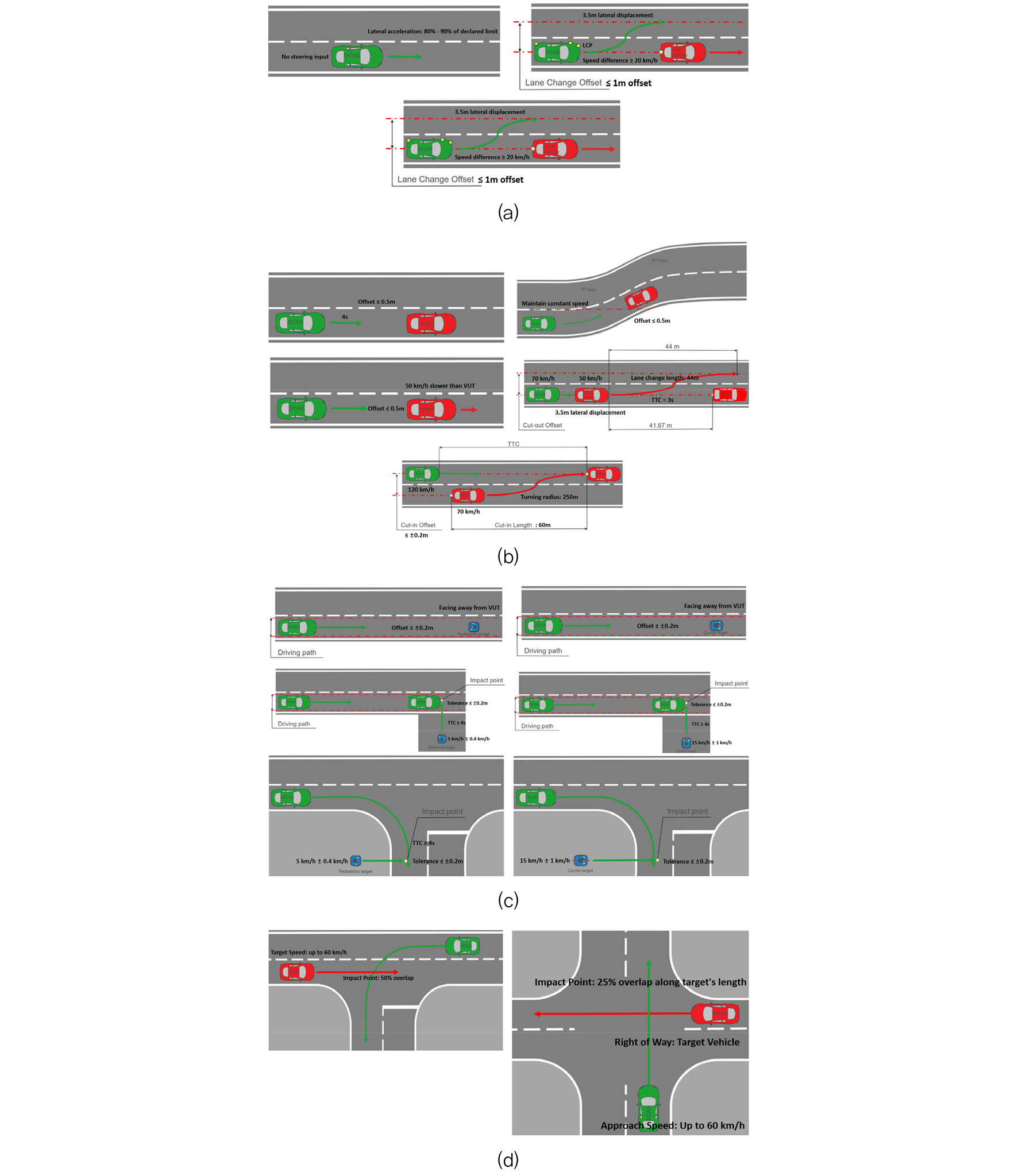
The DCAS must undergo physical testing to verify the manufacturer's declarations, with all tests conducted either by or under the supervision of a type approval or certification body. The tests shall be performed under conditions (e.g. environment, road geometry) that allow the activation of the system or its specific function. The test scenarios shall be designed to verify the system prerequisites for activation of the system and the system boundaries, and to evaluate whether the system is functioning normally based on the declared operational domain, and the type approval body shall perform or at least witness the main test scenarios presented in Fig. 4.(3)Fig. 4(a) consists of scenarios to assess whether the DCAS vehicle reliably maintains its driving lane and whether the lane change function operates correctly. Fig. 4(b) presents the response to obstacles ahead test, which consists of a scenario designed to evaluate whether the DCAS vehicle can appropriately respond to stationary vehicles, slow-moving vehicles, and cut-in and cut-out vehicles positioned ahead of it on both straight and curved roads, and Fig. 4(c) presents the pedestrian and bicycle response test, designed to assess whether the DCAS vehicle can accurately detect and appropriately respond to pedestrians and bicycles. Lastly, Fig. 4(d) presents the intersection driving test, which consists of scenarios evaluating whether the DCAS vehicle can make safe driving decisions at intersections while considering the movement of surrounding vehicles.
Testing is categorized into track testing and public road testing. Track testing is conducted in scenarios that may pose risks to other road users or test operators, such as AEB equivalency assessments and driver unavailability response tests. In contrast, Public road testing is performed to evaluate the system under challenging conditions, including tight curves and complex traffic environments. Table 3. Summarizes these public road test scenarios, which contribute to a multi-faceted evaluation of the system’s behavior and the performance of DCAS under normal real-world operating conditions.
Table 3.
Public Road Test Scenario
The specific test parameters (e.g., current speed of the test vehicle, target type and offset, lane curvature) should be determined by the type approval authority based on the manufacturer’s declaration. To verify system consistency, at least two baseline tests must be conducted to demonstrate reliability and repeatability.
Additionally, extended tests must be performed to verify that the system’s control strategy does not switch abnormally. These extended tests should incorporate test scenarios that combine various parameters and test design variations.
If it is difficult to evaluate difficult scenarios on a test track or in real-world driving conditions, simulation tools and mathematical models can be used to validate safety concepts. In such cases, the manufacturer must demonstrate the scope of the simulation tool, the validity of the relevant scenarios, and the verification of the simulation tool chain (correlation with physical testing).
The key requirements and system aspects for assessing DCAS performance and safety are summarized in Table 4. System aspects refer to functional elements that assess whether the DCAS interacts with the driver and operates safely and reliably. Table 4 outlines each requirement and system aspect to be evaluated in physical testing, and these items should be evaluated at a minimum through track testing or public road validation. In addition, real-world driving scenario-based test methods can be employed to comprehensively validate system performance and reliability.
Table 4.
Test Requirements
4. DCAS Expected Effects and Domestic Implementation Preparation
Implementing technologies that comply with DCAS regulations ensures a minimum level of safety, even if the technology is not flawless, while also minimizing the legal risks for manufacturers—unlike Level 3 autonomous driving technologies. This approach enables manufacturers to adopt and deploy autonomous driving technology in a more practical and scalable manner, ultimately accelerating technological development and commercialization. Furthermore, the standardized integration of driver monitoring systems utilizing HMI is expected to unify the response strategies of Original Equipment Manufacturer (OEM), thereby mitigating potential technical discrepancies arising from variations among vehicles and OEMs.
Meanwhile, as the introduction of DCAS is being discussed in earnest at the international regulatory level due to the official entry into force of the DCAS regulations in September 2024, in order to implement it effectively, it is necessary to establish domestic standards by closely analyzing the proposed requirements and evaluation criteria, and to secure consistency with international standards through testing and evaluation procedures while examining domestic applicability. Therefore, domestic OEMs need to systematically prepare technology development and certification procedures to establish DCAS system that meets international regulations.
5. Conclusion
This paper provides an in-depth analysis of DCAS regulations to assist manufacturers in developing technologies that ensure compliance with these regulations. DCAS is classified as a Level 2 Driver Control Assistance System under SAE J3016, requiring the driver to remain actively engaged in vehicle control and assume full responsibility for any accidents. The system must be capable of safely deactivating or issuing warnings in the event of an emergency or unexpected malfunction, ensuring that the driver can promptly intervene. These regulations are explicitly defined to provide a structured framework that, while not perfect, facilitates the maximum feasible utilization of autonomous driving technology.
The core components of DCAS are categorized into monitoring systems, control systems, and testing and evaluation. The HMI must be designed to provide drivers with a clear understanding of the system’s operational status while simultaneously monitoring them in real time to ensure sustained attention to driving. In terms of control, the vehicle must maintain a safe distance and ensure stable operation in complex scenarios, such as lane merging and intersection approaches, while implementing technologies that ensure compliance with traffic regulations. Additionally, system reliability must be rigorously assessed through various scenarios on both real roads and test tracks, and the validity of the technical documentation and safety strategies provided by the manufacturer must be verified.
The findings of this study systematically analyze DCAS conditions and can serve as a foundational resource for designing DCAS technologies that can be implemented as a practical alternative prior to the full deployment of autonomous driving.
