


1. Introduction
1.1. Styling and Quality Consideration of Clamshell Hood
1.2. Hood Latch Mechanism to Absorb Lateral Distribution
1.3. Benefit and Challenge of Newly Devised Hood Latch Mechanism
2. Prediction and Verification of Dynamic Behavior of Hood System
2.1. Analysis of Dynamic Behavior of Clamshell Hood for the Safety and Durability Performance
2.2. Analysis of Sensitivity for System Parameters
2.3. Vehicle and Component Level Verification
3. Conclusion
1. Introduction
1.1. Styling and Quality Consideration of Clamshell Hood
Line-free styling has become one of the most important directions to provide customers with innovative image of the vehicle.
Typically, long and wide hood styling is one of the design trends to effectively enhance the luxurious feeling of the car. In addition to that, clamshell hood which moves the parting line to the side area is being recently widely applied so as to display the body-integrated image of the vehicle. Fig. 1 shows an example of the application of a clamshell hood for Volkswagen Arteon.

As shown in this figure above, the unique styling characteristics of a clamshell hood whose parting line is located on the side area can be clearly seen. Therefore, one can recognize the frontal image as body-integrated styling so it leads to naturally making the mobility more luxurious and innovative. At the same time, the clamshell hood has the styling point that maximizes the long and wide hood image in its own form. Fig. 2 shows the comparison of the typical and clamshell hood for the same luxury car.
As depicted in Fig. 2, the perimeter of clamshell hood is longer than that of typical one so it is easily understood that the quality of gap and flushness of clamshell hood should be the key considerations of the engineering design. Hence, in order to realize the high-quality alignment of the clamshell hood and body panel, the newly devised hood latch that effectively absorbs the lateral displacement needs to be applied.

1.2. Hood Latch Mechanism to Absorb Lateral Distribution
Fig. 3 shows the hood latch mechanism that absorbs the lateral distribution of panel location. Basically, the gap between the striker and base plate of hood latch is 2 mm for both sides so it alleviates the misalignment of hood panel as possible as it can. Also, the pop-up lever is simultaneously applied to suppress the lateral movement of panel by compressing the striker and claw for the vertical direction.

1.3. Benefit and Challenge of Newly Devised Hood Latch Mechanism
From this mechanism, the quality of gap and flushness of panel is verified from the component measurement as follows. Fig. 4 shows 3D scanning image for 3 mm-lateral misalignment of front end module. In case of typical latch, the amount of lateral movement of hood panel is the same as that of the misalignment of front end module. On the contrary, the newly devised hood latch that absorbs distribution makes misalignment dramatically small so it is clear that it helps a lot to secure high-quality of gap and flushness of a hood system.

However, there is a gap between striker and latch for the new one so it should be noted that the excessive lateral dynamic movement can cause catastrophic disaster such as physical failure of the hood locking system, i.e. it leads to flying away of the hood panel under driving condition.
In this paper, the equation of motion of hood system is derived by Lagrangian method, and the parameters to implement numerical analysis are acquired from CATIA. Especially, the input data processing correlated to the actual response of the system is prepared, and the proper low-pass filter is applied. The numerical analysis is conducted by MATLAB, and the predicted results are correlated to the actual ones. Also, the engineering design guide to make the system robust is suggested from parameter study. Moreover, the actual tests to verify the system are implemented in both vehicle and component level, and the complemented test criteria to validate the system is also suggested from this study.
2. Prediction and Verification of Dynamic Behavior of Hood System
2.1. Analysis of Dynamic Behavior of Clamshell Hood for the Safety and Durability Performance
2.1.1. Definition of Parameters and External Loads
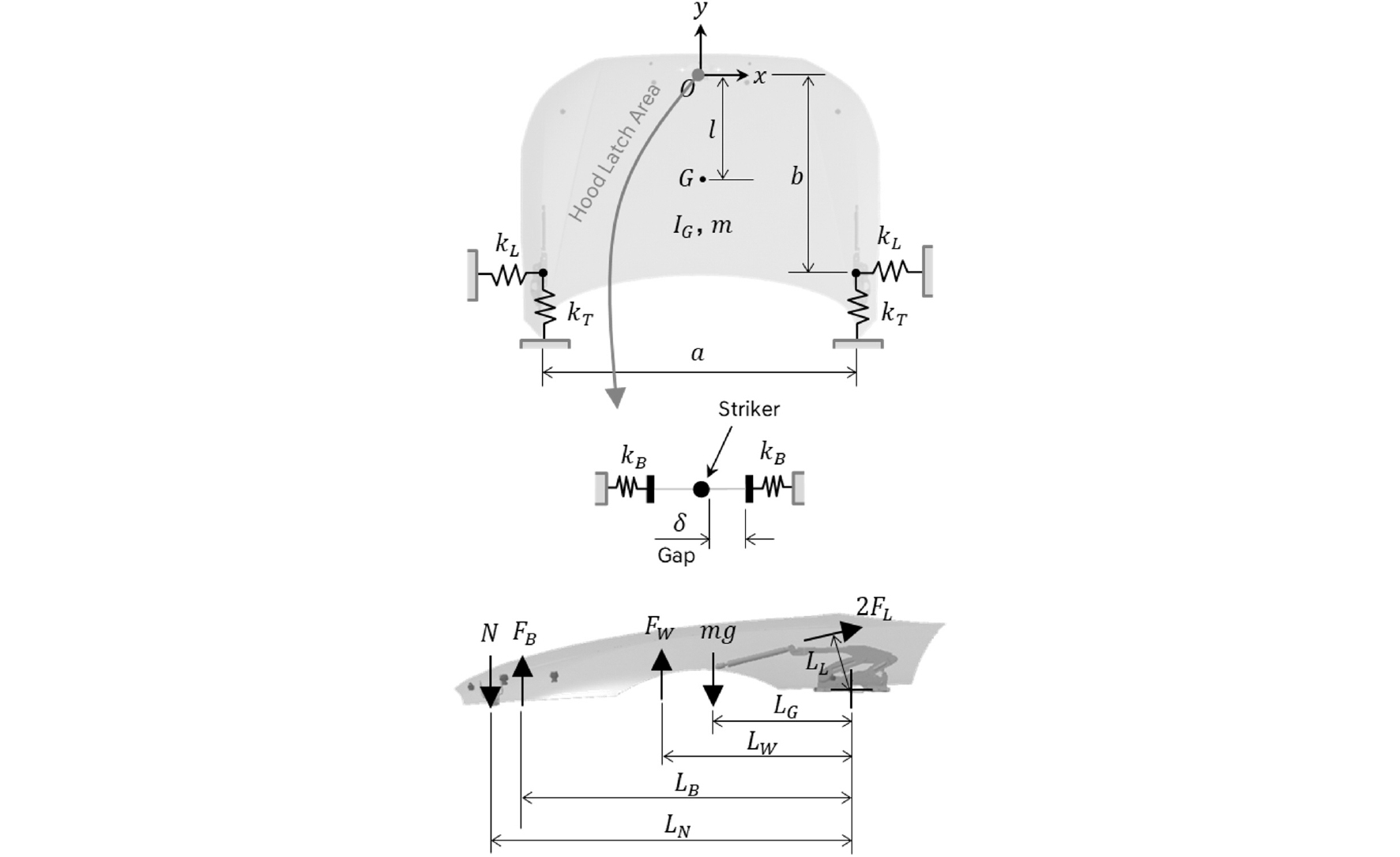
In order to derive the equation of motion, the parameters of the system need to be defined. Fig. 5 shows parameters and external loads of clamshell hood system.
As shown in the figure above, a total of 15 parameters are acquired from CATIA, and three external loads are obtained from the specification of each part. A total of nine displacements - a (1.674 m), b (1.066 m), l (0.565 m), LG (0.507 m), LL (0.023 m), LW (0.572 m), LB (0.936 m), LN (1.057 m), and δ (0.002 m) - are defined. It is noted that 3 external loads of lifter force FL (375 N), weatherstrip force FW (63.8 N), and over-slam bumper force FB (243.3 N) are given in the specification of each part. Also, the mass of hood system m (17.8 kg) is known so the normal force N (182.6 N) exerted on the hood latch can be calculated from the equilibrium equation. Also, mass moment of inertia with respect to the center of gravity IG (8.611 kg) is obtained, and the friction coefficient (μ) is assumed to be 0.35. Then, the stiffness of hinge and latch can be acquired from CATIA static analysis. Since hood hinges are always attached to hood panel, they can be modeled as spring components as depicted in Fig. 5. Thus, the transverse stiffness kT (1,113 N/mm) and longitudinal stiffness kL (62.5 N/mm) are obtained from static analysis. On top of that, the longitudinal stiffness of hood latch kB (3,620 N/mm) only plays a role when the striker contacts the plate of hood latch because there is a gap between striker and latch plate.
2.1.2. Derivation of Equation of Motion for Clamshell Hood System
Fig. 6 shows a schematic diagram of hood system on driving condition.
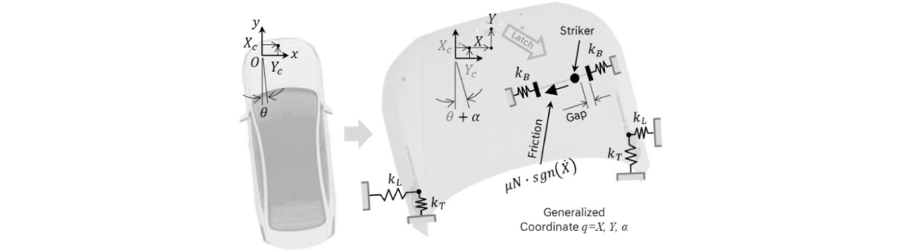
In driving condition, the motion of a vehicle contains translational and angular motion so they are defined as Xc, Yc, and θ, respectively. It should be noted that they generate inertial force on hood system so the generalized coordinates of the system can be defined as X, Y, and α, respectively. Especially, the friction force is generated because of the contact between internally installed pop-up claw lever and striker. Therefore, the direction of friction force can be defined as the signum function whose direction is always opposite to the translational velocity of hood panel.
In order to derive the governing equations of the system, the Lagrangian equation of motion used as follows.(2~4)
where
Eq. (1) is represented as the augmented Lagrange equation of motion. In this equation, q is generalized coordinate, and Qq is non-conservative work term. Also, T is the kinetic energy, and V is the potential energy of the system, respectively. In case that the system has kinematic constraints, the relationship of the constraint , and the Lagrange multipliers λi need to be considered to derive the governing equation. However, if there is no kinematic constraint in the system, the term of Lagrange multiplier of is unnecessary. As shown in Fig. 6, there is no kinematic constraint so is zero. Therefore, the equation of motion of the system is expressed as follows.
The non-conservative work terms of QX and QY are considered on the hood latch area due to the friction and contact force created from latch and striker. The gap between striker and latch is denoted as δ (2 mm) so the values of QX and QY are obtained from the following relationships. If X cos α is smaller than -δ, the non-conservative work terms are expressed as follows.
Also, if the striker does not contact the lateral surface on the hood latch where X cos α is greater than -δ, and smaller than δ, the following relationships can be obtained.
Finally, if X cos α is greater than δ, the following relationships are acquired.
2.1.3. Input Data Processing and Numerical Analysis
In order to apply the most severe driving condition, the Belgian CAE model is basically used to extract input data. In this model, the translational accelerations () are obtained, and the angular terms () can be acquired in a vector manipulation from MATLAB. However, the input data obtained from CAE analysis are not always appropriate to predict the specific system for a certain purpose so they need to be properly correlated to the actual phenomenon in some cases. In this research, the inherent characteristics of the vibration induced from the road surface need to be considered. Fig. 7 shows the camera installation on a front end module and captured image of video footage in Belgian road.

Actually, the actual vehicle response observed in the video footage is about 7 Hz. However, the input data originally calculated from Belgian CAE analysis is far from this actual frequency, which is about 16 Hz. Therefore, the low pass filter that makes input become more precise is needed to consider base excitation.(5) The sampling frequency, cut off frequency, and filter order are defined as 1,000 Hz, 10 Hz, and the 10th order, respectively. Then, the driving frequency becomes closely analogous to the actual one. Fig. 8 shows input data for Belgian driving condition with low pass filter.
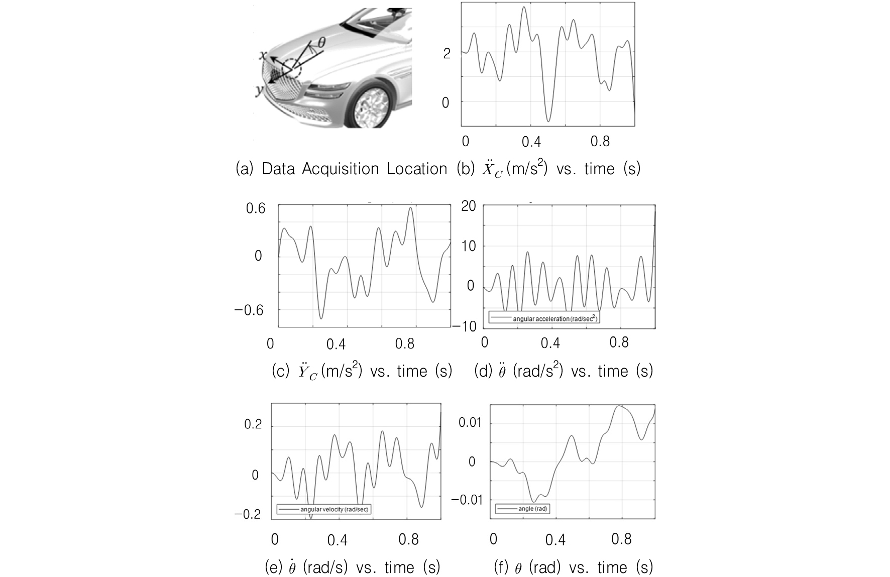
Then, the numerical analysis is conducted by using these inputs. Fig. 9 shows the numerical analysis of a hood system in Belgian driving condition.
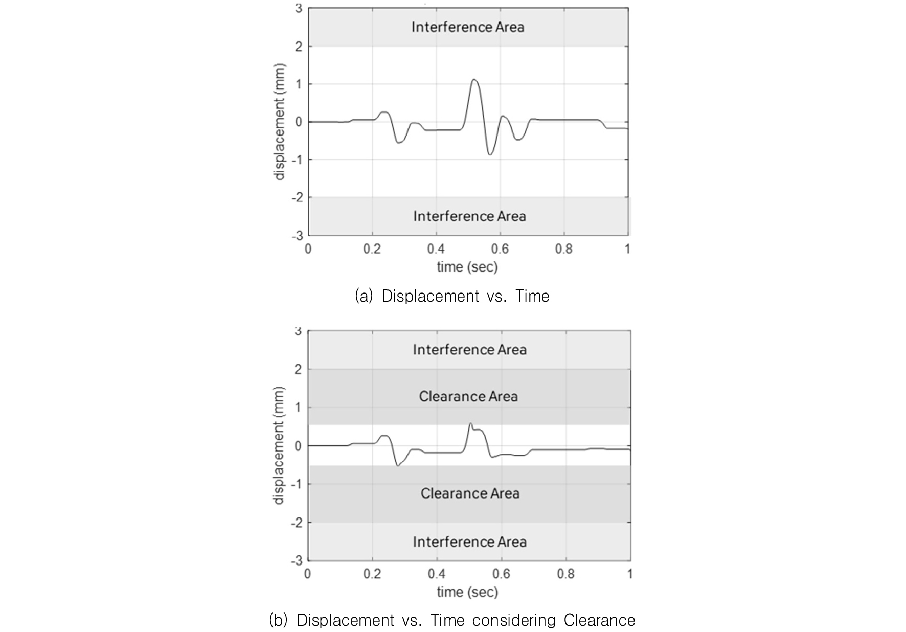
As depicted in figure above, it is obviously seen that there is no contact between striker and latch so the system is sufficiently robust to secure the safety and durability performance. Also, even if the clearance area is considered, the negligible contact that causes small contact forces occurs so it clearly appears that the high-quality of flushness and gaps and core performances of the clamshell hood system can be secured simultaneously.
2.2. Analysis of Sensitivity for System Parameters
2.2.1. Friction Force exerted on Latch and Striker
As depicted in Fig. 3, the pop-up lever is applied to suppress the lateral movement of panel by compressing the striker and claw for the vertical direction. It implies that this mechanism generates the proper friction force that controls the movement of hood panel under the circumstances of vehicle vibration. Theoretically, the friction force can be calculated from the equilibrium condition, and its value is 63.9 N. However, this value incorporates the resisting load such as over-slam bumper force so it is necessary to obtain the pure friction generated by latch and striker themselves. Thus, this value is measured from the following test, and Fig. 10 shows test set-up to measure the friction due to the latch and striker.

As shown in this figure, hood latch is fixed and the push-pull gauge is installed to measure the minimum moving force to overcome the friction force created by the surface between latch and striker. The measured friction force is 51.0 N, and it is noted that there are no resisting forces so the measured value is smaller than the predicted value of 63.9 N from equilibrium equation. Therefore, it is understood that this predicted value incorporates the conditions of external loads such as lifter force of 375.0 N, overslam bumper force of 243.3 N, hood weight of 174.4 N, and weatherstrip force of 63.8 N, which are obtained from the internal engineering specification of each part, respectively. It should be noted that the friction force of the system is always greater than 51.0 N unless the latch system is broken. However, the minimum criteria for each component to secure the friction force needs to be defined to verify the robustness of safety of the system. Fig. 11 shows a plot of external loads vs. latch friction force.
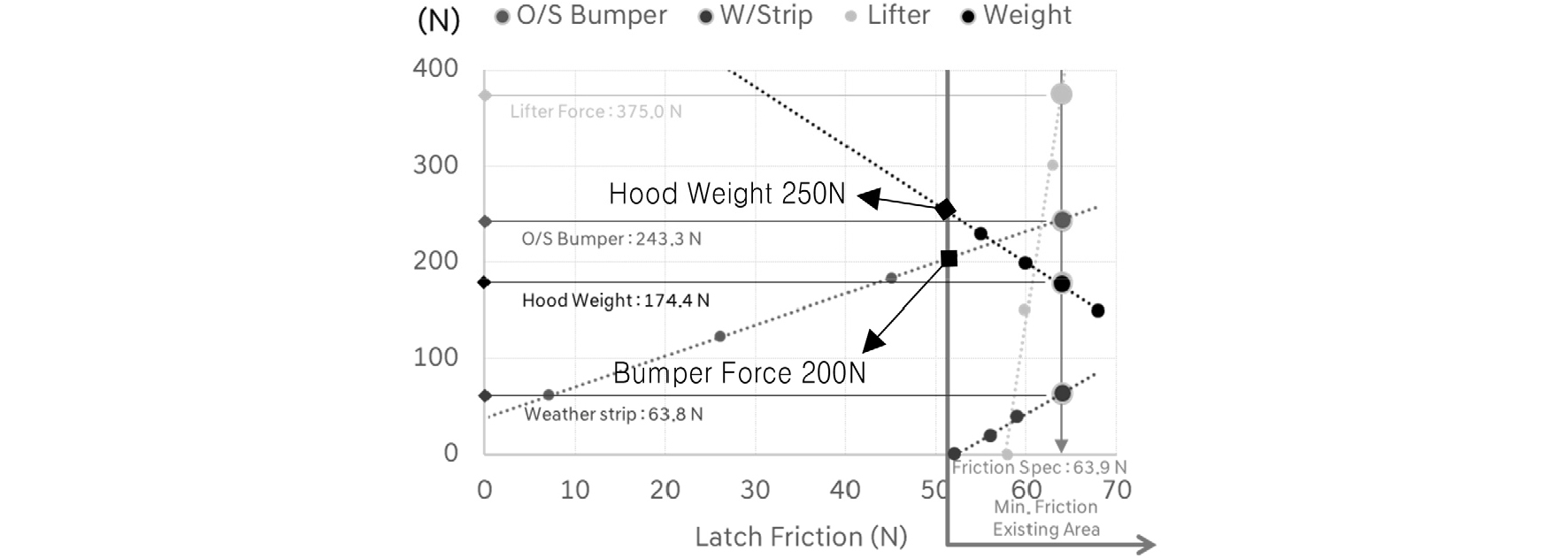
The minimum friction existing area can be expressed as the right area where the friction is greater than 51.0 N. In other words, the friction is naturally greater than 51.0 N because it is generated by the pop-up lever mechanism of hood latch itself. If the friction force is reduced, the movement of hood essentially increases. Therefore, it is important to have the sufficient friction force to suppress the unintentional movement of hood. As shown in this figure, it is seen that the overslam bumper reaction force and the hood weight are the most sensitive factors to reduce the friction. Therefore, the parameter study of them needs to be implemented to confirm the stable performance of safety and durability.
2.2.2. Sensitivity of Overslam Bumper Reaction Force
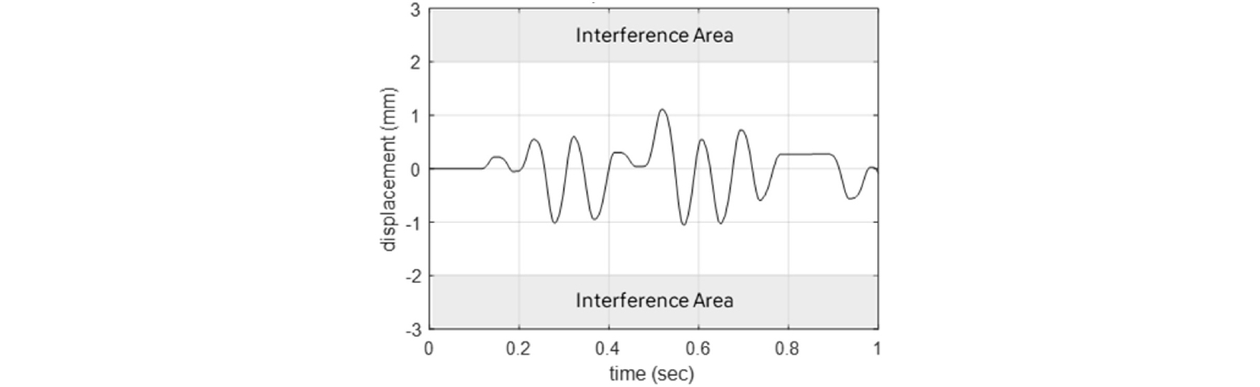
Fig. 12 shows the displacement vs. time at bumper force of 200 N.
It is obviously seen that, as the overslam bumper reaction force is reduced, the friction force is also reduced. As seen in Fig. 12, it is clearly seen that there is no contact between striker and latch because the pop-up lever mechanism creates enough friction force in the latch. In other words, even if the overslam bumper reaction forces are lost by some reasons, there will not be any undesirable movement of hood panel. From the simulation, the contact between latch and striker starts from the friction of 22 N. Therefore, in order to secure the stable essential performance of the system, it is suggested that the minimum friction of hood latch needs to be greater than 50 N before durability test, and 30 N after durability test, respectively.
2.2.3. Sensitivity of Hood Weight
Fig. 13 shows the displacement vs. time at hood weight of 250 N.
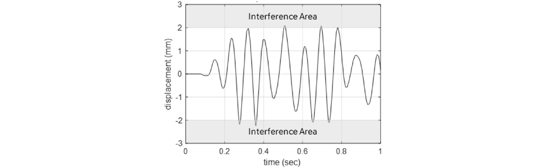
As shown in this figure above, the contact is recognized because of the increase of hood weight. It is naturally understood that the amplitude of the response should increase when the hood weight increases because of the inertia effect. From the simulation, the contact between latch and striker starts from the hood weight of 225 N. Therefore, in order to secure the stable key performance of the system, it is suggested that the allowable hood mass needs to be less than 22 kg.
2.2.4. Sensitivity of Hood Hinge Stiffness
In order to ascertain the effect from the increase of hood hinge stiffness, the prediction of dynamic behavior of hood panel is implemented under the slightly augmented hinge stiffness value. Fig. 14 shows the displacement vs. time at 10% increase of hinge stiffness.

As shown in the figure above, it is seen that the lateral stiffness of hood hinge does not have an influence on the movement of hood panel. There seem to be no change of dynamic behavior of hood panel as the change of stiffness of hinge.
2.2.5. Sensitivity of Air Flow
When a vehicle is moving, there exists aerodynamically induced load on hood latch retention system. Figure 15 shows the types of aerodynamically induced loads in driving condition.

As shown in this figure, air flow induces two types of loads on the surface of hood. The vertical force plays a role in suppressing lateral movement of hood because it raises the friction of hood latch and striker. However, the lateral force created by the lateral air flow affects a lateral movement of panel. In a reference,(6) lateral force can be generated up to 250 N when a 2 door Coupe drives at the speed of 272 km/h. This amount of lateral force is corresponding to the input of 10% for the Belgian condition so the predicted results are obtained from the numerical analysis as well. Fig. 16 shows the displacement vs. time for 250 N lateral induced load.
As shown in Fig. 16, the lateral movement is not observed at the numerical analysis and it is hardly seen that a vibration is recognized at the speed of 200 km/h. Thus, the aerodynamically induced loads do not seem to affect the undesirable movement of clamshell hood panel.

2.3. Vehicle and Component Level Verification
2.3.1. Vehicle Level Verification
In order to verify the safety and durability performance of the system, it is necessary to confirm major four tests in a vehicle level, i.e. there are Belgian, combined road, fleet, and open-close durability tests, respectively. From these tests, there are no functional failures for the whole conditions. Typically, small scratches on the surface of a striker occur, but it does not result in the functional failure such as breakage and corrosion of the system. Thus, it is seen that the reliability of the safety and durability of the system is verified from the standpoint of vehicle level.
2.3.2. Component Level Verification
Basically, hood latch needs to have a sufficient strength to hold a hood panel assembly so it is validated by the resistance of the vertical static load. It is noted that the gap between latch base plate and striker to absorb the distribution so the direction of the force exerted on the hood latch needs to be considered from the perspective of the degree of severity. Fig. 17 shows a test rig setup and test sample for an oblique condition.

In this setup, the oblique angle is 35 degrees and the amount of strength is over 7,000 N. Typically, the amount of hood latch strength for the vertical normal direction needs to be greater than 5,400 N so it is clearly seen that the strength of this hood latch is sufficient to have an expected performance.
3. Conclusion
The equation of motion of hood system is derived from Lagrangian equation, and the numerical analysis is implemented by using MATLAB. The predicted results are obtained from the numerical simulation, and it is shown that there is no contact between striker and latch base plate, i.e., it is indicated that the safety and durability performances are sufficiently secured for the system. Especially, they are correlated to the actual video footage recorded from Belgian road test, and the predicted results are well in coincidence with the actual dynamic behavior.
Then, the parameter study is conducted to figure out the sensitivity to affect the movement of hood panel. It is noted that the friction force generated from the latch mechanism and striker needs to be secured, and the resisting force of overslam bumper and the weight of hood panel are major key factors to have an influence on changing this friction. In consideration with the loss of resisting force of overslam bumper, it is suggested that the minimum friction force generated by hood latch pop up lever needs to be greater than 50 N before hood opening and closing durability test, and the force should be greater than at least 30 N after the durability test, respectively. Also, in consideration with the weight of hood system, it is suggested that the allowable mass of hood panel needs to be less than 22 kg to secure the friction force. For reference, the stiffness of hood hinge and the aerodynamically induced loads on the surface of hood panel do not create the undesirable lateral vibration of hood in driving condition.
Besides, the safety and durability of clamshell hood system is verified on not only vehicle but also component level. A total of four safety and durability tests on a vehicle level show that there is not any kind of functional failure. Also, the strength test of the part for the oblique direction is also conducted and it is shown that the sufficient performance is validated as well.
From this study, it is obvious that the catastrophic failure such as flying away of hood panel in driving condition is sufficiently prevented. Moreover, it can be said that the high quality of gap and flushness is effectively realized by the lateral adjustment implemented from the appropriate gap between hood latch and striker.